
Arx IP for a GFSK Receiver
This page presents a simple GFSK receiver that consists of 4 IP blocks. They have been designed by means of a system-level design methodology that combines Arx with IT++, an open-source C++ library for mathematics, signal processing and telecommunications. Check the links below to download all code and a detailed technical note on the GFSK IP.
| Description | Download |
|---|---|
| Tar ball containing all code | gfsk01.tgz |
| Technical note | gfsk01.pdf |
The text below is a short summary of the technical note.
GFSK, Gaussian frequency shift keying is a modulation scheme for digital transmission used in various standards including Bluetooth, DECT and Wavenis. It basically amounts to frequency modulation where the carrier frequency is increased to transmit a '1' and decreased to transmit a '0' (or vice versa). The frequency transitions are not abrupt, but smoothed by a Gaussian filter.
The parameters of the GFSK system presented here, are not taken from an existing system. These are the specifications:
- Analog circuitry is not modeled. The modulation is centered around an intermediate frequency (IF) of 1 MHz.
- The signal is sampled at 8 MHz.
- The symbol rate is 0.5 MHz, meaning that each symbol is represented by 16 samples.
- The modulation index is 0.5.
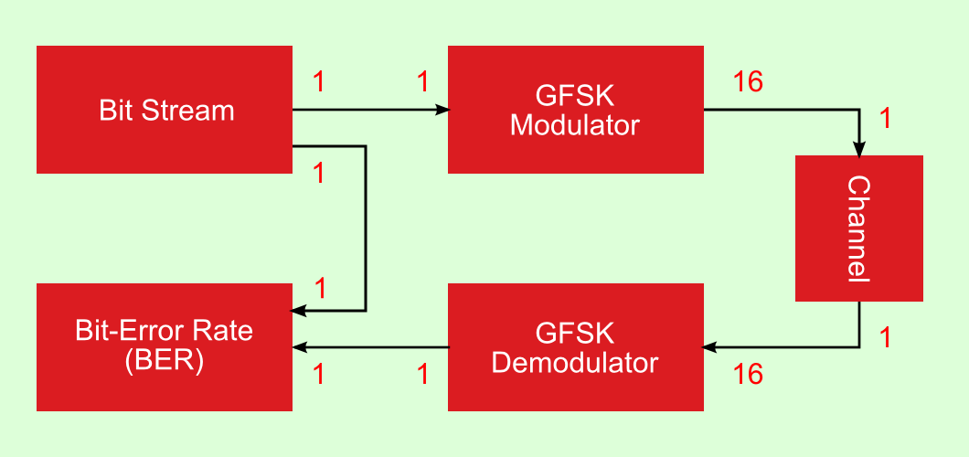
The system model, which acts as well as testbench for the receiver (demodulator) has the structure shown below. IT++ code is available for both the modulator and demodulator.
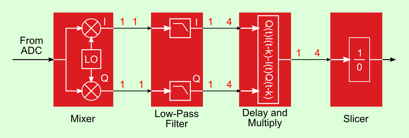
- The mixer consists of multiplications with sine and cosine functions in IT++ and of a CORDIC in Arx.
- The low-pass filter (LPF) is a symmetric FIR filter the coefficients of which are mostly powers of 2. This makes it attractive to design a "multiplierless" implementation as done in the Arx code. The coefficients have been taken from [1].
- Only one out four samples computed by the LPF are used by the next block. An efficient implementation of the FIR filter would therefore use a polyphase structure. This is not the case in the current version of the Arx code.
- The delay-and-multiply block does the actual demodulation, using a well-known method for FM demodulation [2]. Ideally, it outputs four positive samples for each received '1' and four negative ones for each received '0'. The noise disturbs this ideal situation.
- The slicer, finally outputs the bits by adding four input samples and checking whether the sum is positive or negative. Summing acts as a filter improving a bit the effects of noise. The current receiver does not contain circuitry for synchronization. An optimal default value for the correct synchronization moment is hardcoded in the testbench; this moment can be chaged by command-line options.
References
- [1]
- Langlois, J.M.P., D. Al-Khalili and R.J. Inkol, Polyphase Filter Approach for High Performance, FPGA-Based Quadrature Demodulation, Journal of VLSI Signal Processing, Vol.32, pp. 237-254, (2002).
- [2]
- Park, J.H., An FM Detector for Low S/N, IEEE Transactions on Communication Technology, Vol.COM-18(2), pp. 110-118, (April 1970).